CD 33 Refit: Embrace the Ω .

Best practices and electrical components have improved a lot since 1980. So for Sanderling, and the upgrades I was interested in, I totally embraced the Ohm. Some boat systems can be jury rigged. But the electrical system isn’t one of them, especially not if you plan to increase demand on the existing system.

Sanderling’s DC panel – typical ’80s

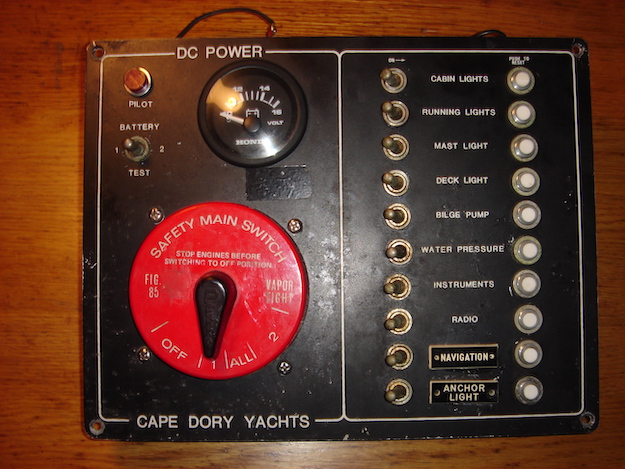
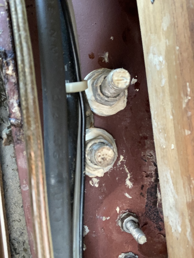
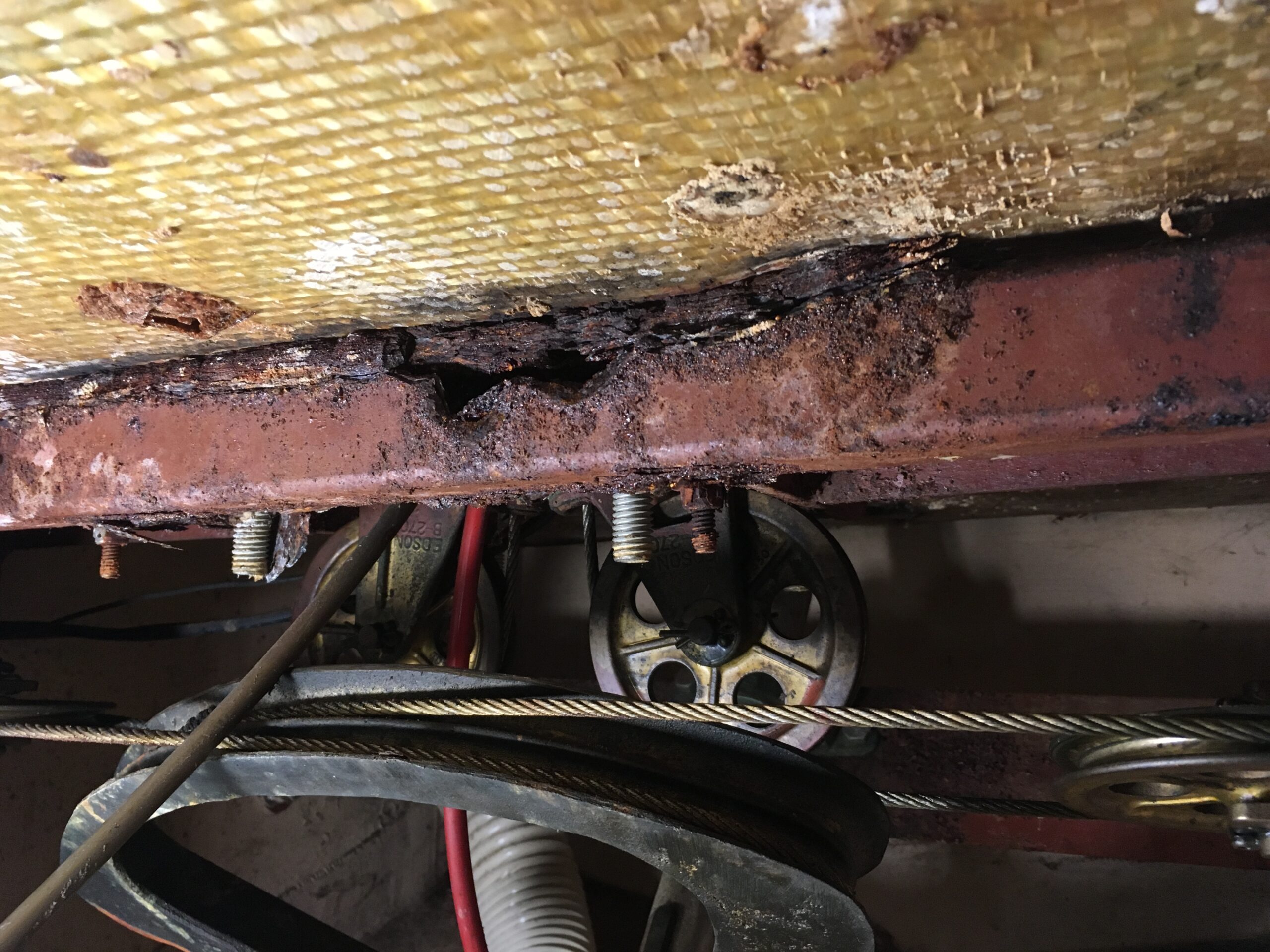
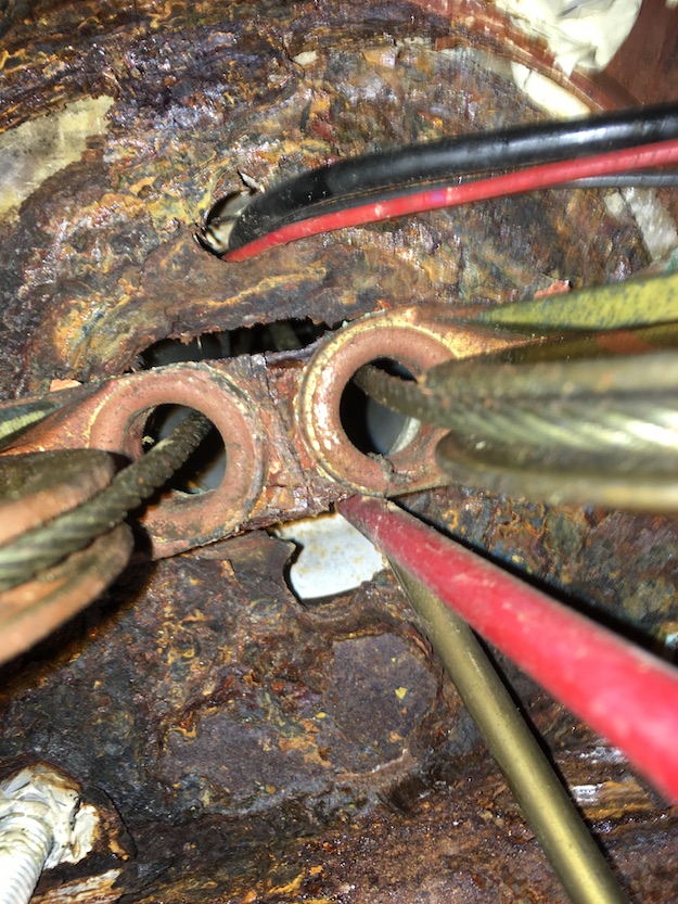
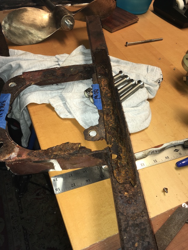
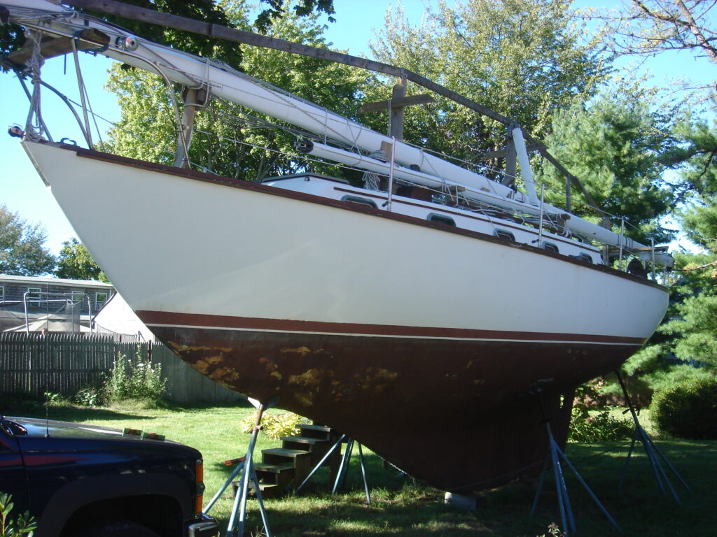
Surveys don’t include any significant analysis of wiring or the electronics those wires serve. So for any new owner, documenting the status of the existing system is always a good first step even if you don’t plan to expand. Sanderling had very basic components sparsely wired for DC circuits (note the 10 AWG wire off the common post serving all the breakers). The main hot bus is a solid copper wire, soldered in through the feed side of all breakers like a backbone. Typical 1980’s. She also had a jury rigged AC system using a residential sub-panel box that had turned to rust, probably because her original AC panel was damaged and removed.

DC panel feeder for Sanderling was 10 AWG – single copper wire loosely soldered in as hot bus

So for Sanderling the long term plan was to upgrade her systems from a 1980’s weekender to a cruiser with a few amenities and room for expansion. For me that did not mean frozen ice cream and HD TV for a week at anchor without running the engine. It meant being able to run pumps, electronics, or even the autopilot for certain periods if I chose not to run the engine (or couldn’t run the engine). I created a spreadsheet to actually anticipate what kind of power I would need for sailing, motoring, or anchoring. That helped me estimate the size of the battery bank I would need, and also the kind of charging I would need to keep the batteries happy.

adding up loads and Amp Hours needed

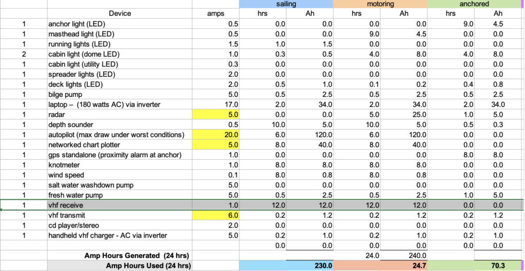
Sailing and motoring needs differ depending on variables like how often you manually steer vs. using an autopilot, alternator output, etc,. After figuring out what I wanted the boat to be able to do in various scenarios, I estimated the amp-hours each scenario would require over a 24 hr period. Then I subtracted any amp-hours that might theoretically be replaced in that same 24 hr period from charging sources during each scenario (surplus alternator amps, solar panels, wind, etc,.)

the overall design for Sanderling – large house bank, dedicated start bank, high-amp fuses, sub panel

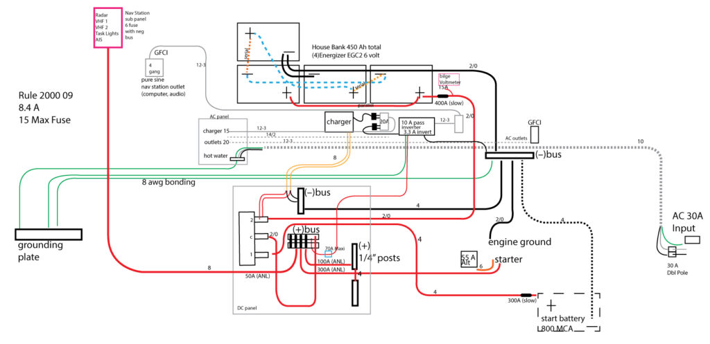
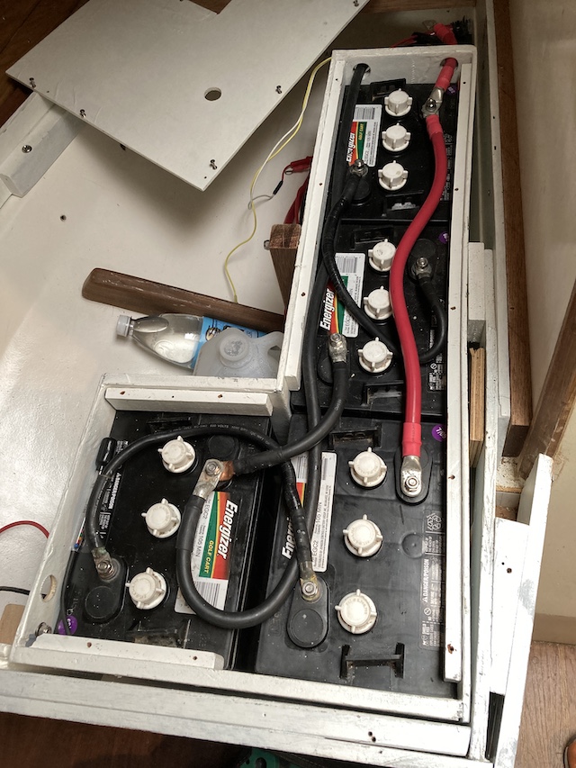
The sailing scenario above (230 Ah) would require the most from the house batteries. If you use Calder’s 50-80 rule (never go below 50% state of charge, and charge to 80% in regular use) then I would need a house bank with total capacity of 650 Ah to actually get a usable 200. But space and cost were factors, so I compromised by installing four golf cart batteries (6 volt) that would produce a bank with total capacity of 460 Ah. To get my 200 usable amp hours for the most demanding scenario, I’d have to either charge to 100% (time consuming), install a solar panel to offset consumption, or ration the 138 Ah I would have if the house bank was only at 80% charge.

DC Bus bars and terminal block (solder gun to remove sketchy old soldered connections)
  • Four 6 volt deep cycle in series/parallel to create a 12v house bank with 460 Ah
  • Dedicated crank battery (750)
  • Pure sine inverter (isolated circuit for laptops, or any sensitive tech)
  • Modified sine inverter for miscellaneous (undiscriminating) devices
  • Rewired and labelled DC panel busses and connections
  • 2nd DC panel for expansion
  • Custom AC panel in new location
  • DC sub panel at Nav station (with alarm panel)
  • DC outlets and USB charge ports at Nav Station & cabins
  • High Amp fuse bus
In my CD 33 I chose to raise the quarter berth 3.5 inches to accommodate the height of the golf cart batteries in custom fiberglass box

For the upgrade every connection and circuit was replaced, except the original circuit for the cabin lights (which would now serve low power LEDs) and the existing galley/cabin GFCI AC outlet branch circuit (which was a still healthy “direct burial” Romex 12-2 with ground). I fished wire in places I did not know existed on a Cape Dory! But the panel design and bus wiring was done through the winter on the bench in a toasty warm workshop.

new teak plywood cabinet face, main and aux DC panel cut-outs

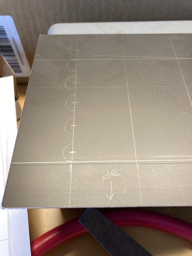
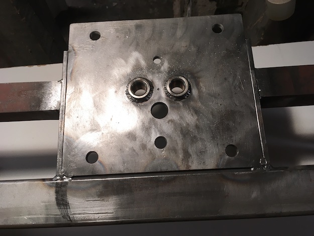
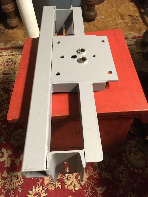
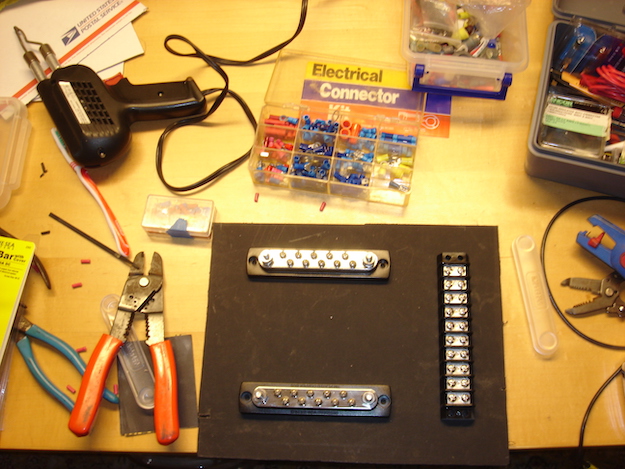
I found a source on eBay for 1/8 inch aluminum plate that had a nut-brown finish on one side that looks good with the CD interiors. So I decided to just make my own panels from scratch (I also could not afford Blue Seas products). It’s not difficult to make a jig out of hardwood so you can drill out all your holes in consistent rows. With a special multi-step drill bit you have all the sizes you need in one bit, and the aluminum is easy to work with.

Carling technologies sells replacement toggles (match toggle, wire, and breaker specs to the load)

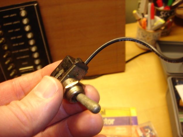
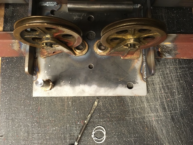
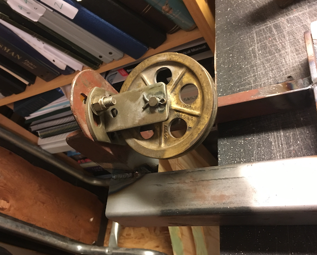
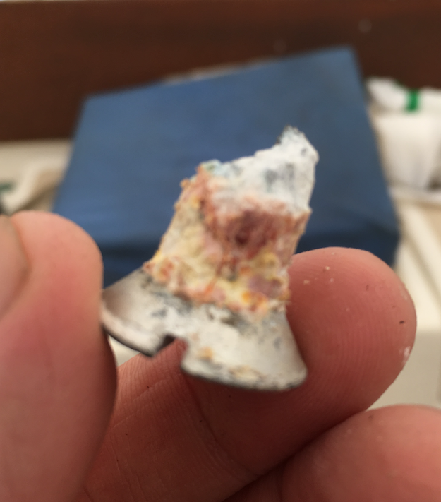
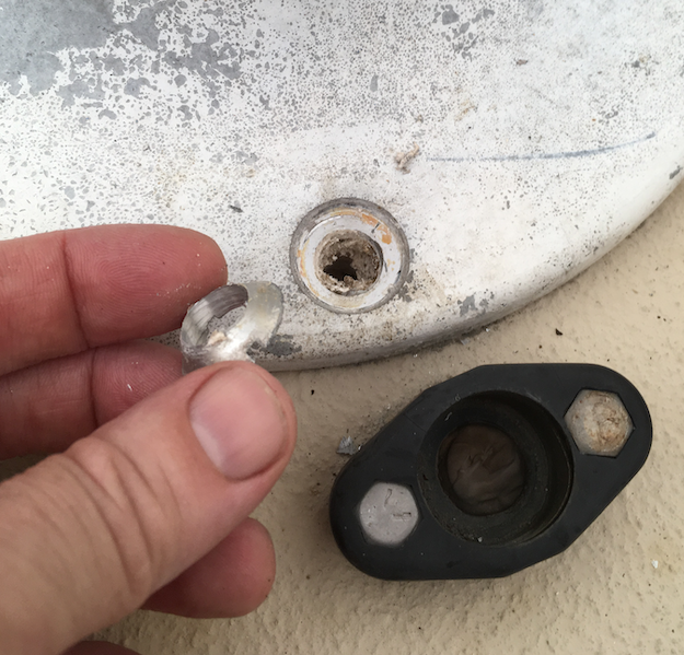
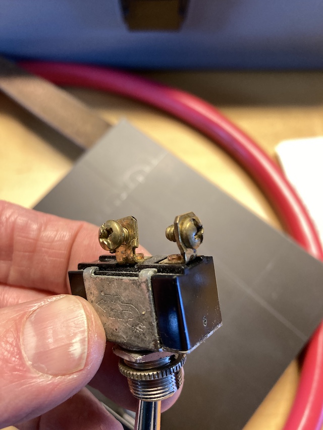
Updating your electrical system doesn’t mean replacing it entirely ($$$). These original “aviation” toggles used by Cape Dory are rated for 6A @12 VDC (ok for small loads). But the older ones have 16 AWG pigtails (only rated a mere 10A if the circuit is*under* 6ft length). That doesn’t meet todays standards if the switch follows a breaker rated higher ( 15, or 20 Amps). Cape Dory seems to have just used the same low amp toggle for all circuits regardless of the rating of the breaker, even for AC circuits. And depending on who makes the switch, the AC rating and DC rating may not be identical. I have seen these older toggles heat up considerably on AC panels with loads that did not trip the breaker.

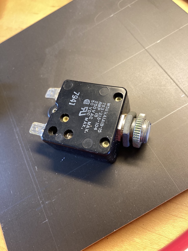
So the toggles are fine to replace as long as you purchase a quality switch rated *at or above* the 12 VDC amp rating (or 125 VAC rating) of each particular circuit’s over current protection. Use the same gauge wire for the entire circuit, and get replacement toggles with ring terminals instead of solder or blade connectors. The same applies to replacing a push-button breaker, you can buy them with ring terminals instead of blade.

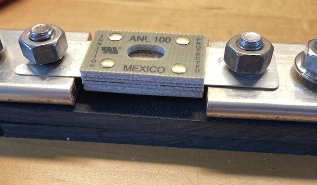
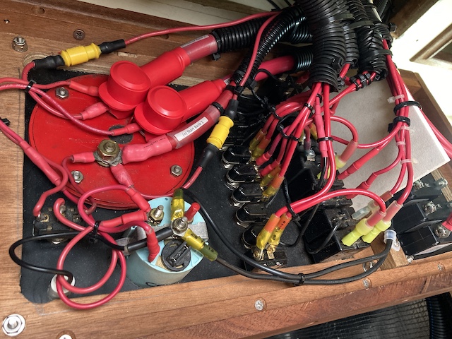
Best practice these days is also to fuse every circuit at the source. There is an ABYC exception for “starter circuits”, so you can still forego the fuse at any battery that might be used to start with, but it has become common practice to have a high-amp slow blow fuse at each battery bank.

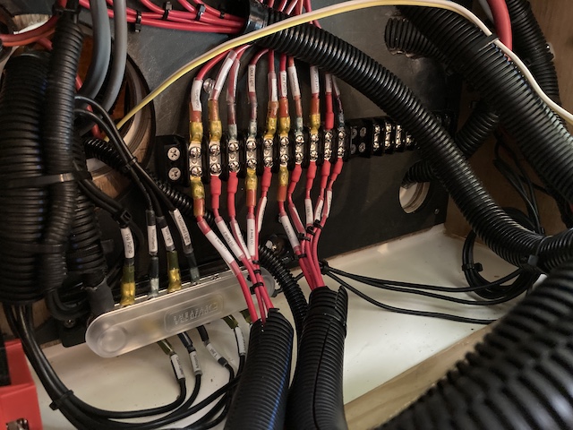
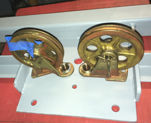
For making your own busses you can buy tin coated 110 copper bar online. You can lookup the conductivity ratings so you know you have a thick enough bar. For my purposes, a 1/4″ thick by 1 -1/2″ wide bar exceeded the combined amperage loads of the fused circuits it would serve.

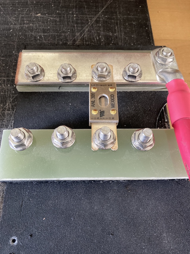
The completed high amp fuse block is fed by the common pole of the selector switch. The fuses off this block feed the DC panel hot busses, the starter circuit, and the inverter, with room for expansion.

custom high amp fuse block

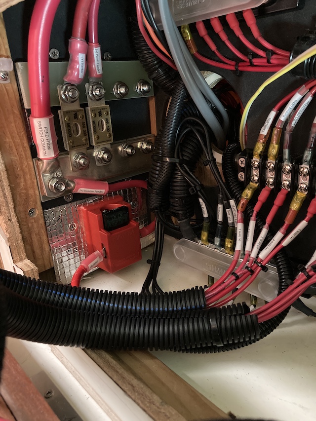
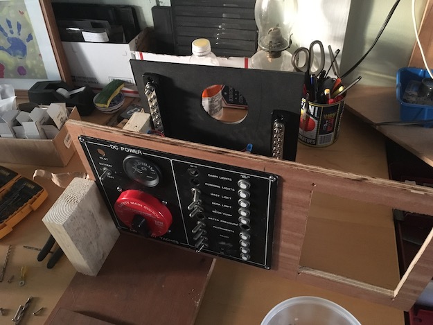
If you decide to keep using the toggle switches, you’ll need a terminal block to organize the load side (from toggle to actual circuit). The line sides of the push-button breakers are all connected directly to the hot bus. That is one advantage of replacing all the push button/toggles with magnetic breakers instead (if you have the $). Because in that installation the hot bus is integral to the breakers on the panel, and you could eliminate the intermediary terminal block shown in my installation above.

custom panel for additional DC circuits – including indicators for voltage at each bank

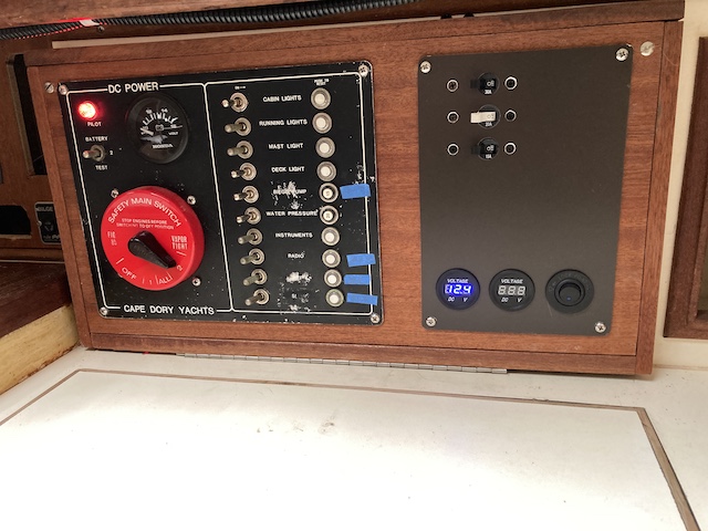
But also consider that a terminal block is still good for organizing, and stand-alone hot busses can be useful for expansion. Here’s the additional DC panel (above right) using magnetic breakers. The pumps and sub-panel main were all put there using magnetic breakers, keeping the boat’s low-amp circuits on the original push-button panel. The two digital voltmeters are wired to show voltage for each bank measured at the battery terminals (not off the selector switch).

circuits all labelled with clear shrink tube
Hybrid solution (added second DC panel with magnetic breakers for high-load circuits, replaced some older taggles, eventually will replace all toggles and probably replace selector switch.

CD 33 Refit: Get some sole

The cockpit sole was soft when I purchased Sanderling, but the side decks were solid. Soft side decks would have been a deal-breaker. But a cockpit sole is not too difficult to rebuild especially if you have already removed your rusty steering bracket to be rebuilt (see the Clunk post). I was certainly not going to install my new steering bracket under this cockpit sole and see it quickly destroyed by a leaking pedestal.

top layer lifted off without any effort, there was nothing holding anything together

Sanderling had been on the hard covered for 7 years. I needed to determine how far the core rot had progressed. My tapping skills proved pretty good. I had estimated that from the aft end to about a foot before the bridge deck the core was punky. I did my cuts and removed the top layer. The plywood and balsa core around the pedestal was just dust, and the balsa towards the bridge deck was rotted and still holding water.

top layer off
underside of removed cockpit sole

I used a simple circular saw and common blade to cut just enough depth to penetrate the top layer of glass over the core. I used a piece of square profile wood trim as a straight edge in between the saw and the locker side walls. Where the blade fell short of completing the cut in the corners (too cramped) I finished the cut with a cutting wheel. I got the top layer off in two pieces.

cockpit revealed
the top layer came right off, nothing holding anything together

There was a seam of epoxy within the core about a foot from the bridge deck. So my tap guesstimate of the rot lined up with that. But water had made it beyond, that seam just made things sound solid while tapping from above. So I made a second cut removing the rest of that area of top layer. The balsa in that second piece was still adhered to the top layer, but as I pulled it up a thin layer of the moisture weakened bottom layer came up with it.

I chose not to re-use the top layer. It was tired and warped by water intrusion, with delamination at the pedestal bolt areas. The new sole would be synthetic core with layers of chopped strand and bi-axial glass.

cross section plan of layers – not to scale

The original top layer of the cockpit was a full 1/4 inch thick. I had probably an 1/8 of an inch sag in the bottom layer from age, and the Divinycell (closed cell) core material was not as thick as the original balsa. So after the core was glued in first onto the bottom layer I’d need to build up almost one half inch of glass in order for the whole thing to be flush with the original sole. That worked out well as I’d rather have a very stiff and solid sole since it’s a high traffic area.

cockpit sole revealed
old balsa core removed, bottom layer remains, styro core cut into strips to act as cored edge flange

There was no way to cut an oversized continuous piece of core that would fit into the 1 1/2 inch edge cavity. And I did not want to leave it as a void. So I cut strips out of foam core with double taper and glued them in first using epoxy with filler.

This would stiffen the edges and give the big piece of core a 45 bevel to sit on and glue to. You can see the step I made with the router. Not necessary to make the edge pretty since after epoxy, fairing compound, sanding and paint layers you won’t be able to tell anything happened.

emerg tiller port
patch job by builders on misaligned tiller port

I also noticed from below that original builders had drilled out the hole for the emergency tiller in the wrong spot. Looked like they moved the hole back an inch and filled in the missing bit with a kind of crescent moon shaped plug. So when I glassed in the new sole top layer I was able to cut a fresh new hole out for the emergency tiller hatch in the correct spot. (tip – leave a bit of wiggle room with the hole and dry fit your emergency tiller hatch & tiller to ensure proper position)

foam core (Divinycell)

Bottom layer of cockpit sole wetted out with epoxy first. Single piece of foam core with reverse 45 bevel, sitting on the previously glued in 45 bevel edge strips. Weights applied to press core down while setting up. (tip-put plastic below to catch drips) The position of holes for the new core were marked from below by tracing the position of the existing bottom layer holes. The two extra holes seen here on either side are recessed cavities in the core for the heads of the bolts that hold the first two sheaves in place below (going through the steering bracket). The third extra hole serves the same purpose for the quadrant stop, also bolted in to the bracket below. The layers of glass just covered them up but when the steering bracket was installed it fit flush because those bolt-heads could tuck up into those recessed areas.

routered out a step in the edge of the cut – so this first piece of bi-axial put down covered the core, the

After routering out a 1/8 inch step in the edge of the top layer, I could put the first layer of bi-axial down and it would cover the core, the seam of the 45 bevel edge core I put in, and at least 1/4 inch of the original top glass layer (see illustration above)

first layers of bi-axial tie everything together at the edges

The larger holes were visible enough through each new layer that I could find their center and use a hole saw. But the pedestal bolt holes were hard to see. I didn’t want to have to drill out the holes from below. So I got some short pieces of 1/2 inch PEX and their actual OD was perfect for leaving room for the bolt and bedding. I just stuck them into the bottom layer pedestal bolt holes and built the glass up around them. This kept the holes exactly where they needed to be.

The bottom layer of the cockpit sole sloped a bit towards the bow, so as I built up layers the aft end was rising faster by an 1/8 of an inch or more. So I used fairing compound layers in between, and in the end had to use something bulkier, so I used up some remaining woven cloth. I built a squeegie out of a 2×4 and a piece of PVC trim that was the width of the cockpit, and used that to check the build-up, and to scrape the final fairing layer even with the edges.

some waves on 2nd layer of fairing – but after sanding each layer it all evened off. I also spot fixed certain low areas with a smaller applicator before doing next layer.
about six layers of fiberglass, layers of fairing in between (top fairing layer pretty thick)
a 2×4 with PVC edge used for squeegee – made sure everything was level with original edges
the new cockpit sole is an inch thick (1/2 in of core, 1/2 in of glass)
primekote two-part primer (Interlux) two layers
Interlux Brightside single part

The color of my non-skids was somewhere in between the neutral look of Grand Banks Beige and the warmer look of Bristol Beige, so I bought a can of each and mixed them.

building up layers of Brightside (first layer sanded well before second layer)
Too coffee colored, added more Bristol Beige to the mix for the next layers
fall evenings getting cooler, heat lamps to help curing. Five layers (single part Interlux needs buildup)
final color 75/25 mix favoring Bristol Beige – a perfect match!
for non-slip I used Intergrip powder, broadcast on wet layers and rolled on with impregnated paint

I actually lightly sanded my layers of broadcast non-skid after drying, because I did not want an abrasive surface that stood out against the worn nonskid on the rest of the boat. Then I switched to impregnating the paint with the nonskid and rolling on with a hard mottle roller, that worked great and helped move and evenly distribute the nonskid (the brush was no longer useful on a rough surface). I did two coats of paint over the two-part primer first, then build up about 3 or 4 more layers of paint and light nonskid. The results are much better than I expected, not having done any nonskid before. It looks good without making the rest of the worn out nonskid in other places look bad.

CD 33 Refit: Clunk!

I was moving the rudder back and forth one day (on the hard) to check the swing, when I heard a CLUNK below the cockpit sole. I looked around and found this little beauty. This is the rudder stop that was welded to the steering bracket. It stops the quadrant from turning too far either side.

rudder stop
rudder stop

Cape Dory builders made use of generic steel in certain internal areas. The steering bracket and the horizontal backings for shroud pad-eyes are two such areas. When surveying a Cape Dory, these are two places to check first for corrosion. My chainplate systems were in good shape when I surveyed Sanderling for my own purchase, and still are. Just a little surface rust in a few spots.

looking up at the hull-deck joint area port side

But the steering bracket was corroded even when I purchase her. So the time to deal with it had finally come with the rudder stop going CLUNK! Tied to this project was a pedestal renovation and cockpit sole rebuild, since the long standing water intrusion also got into the sole core (see the post Get Some Sole).

pedestal leaking for many years – serious corrosion (bronze quadrant and ss wires spared)

The stock metal used in these areas was only covered with a slim coating of what appears to be primer by Cape Dory builders. The leak in this area was due to either poorly bedded pedestal at build (others have suffered this condition), or movement of the pedestal over time, which compromised the caulking. Lots of water came through here. There was most likely galvanic corrosion also.

cable guides
cables coming out of pedestal – not much left of backing plate

The pedestal backing plate on these Cape Dory boats came with the Edson steering solution kit they used, and Edson calls it the cross-wire idler. It was a fairly thin piece of cheap metal in the 1980 version, and was actually a weaker link in this system than the original metal Cape Dory used to fabricate the rest of the overall steering support system under the cockpit sole.

used idler plate
what the original Edson idler plate looks like – (pic from someone selling a used one on the internet)

I do not believe Edson has any of these older idler plates. They pointed me to the new versions when I inquired. They are $459 (not cheap) and made of aluminum. Edson was only interested in selling me an entirely new system. But on my salary there was no way I was going to toss out my bronze sheaves for costly aluminum ones. They were still in great shape.

When I got my rotted steering bracket out it looked like Cape Dory builders had just welded the Edson provided idler plate onto their yard-fabricated bracket that holds three things together ( pedestal idler, the four sheaves, and the rudder stop) . You can see below the original Edson idler plate attached to my CD fabricated steering bracket was almost entirely GONE.

rotted backing plate

The two outboard sheaves were still OK. So I had a local fabricator take the entire thing and cut away all the bad stuff, and he made a replica using stock metal for about $400 (New England area price). Down south you can probably get it done for half that.

new steering bracket

I had him embed two stainless grommets as primary wire-guides that were machined to take retaining rings, so the sheaves would mount on them as before and swivel to adjust, but could be removed if needed. On the original Edson idler these were press-fit ss grommets that allowed the sheaves to swivel but made them permanently fixed to the plate. I also called for a 1/4 inch thick idler plate, and a rudder stop that would be removable for doing maintenance on the quadrant area.

there was enough room to double-up the clip rings on each, so it was snug but could still swivel

I did not get fancy with machining a swing arc for the hold-down bolts like the original Edson plate had. There was no need since it was not going to be critical to continually adjust the positions of these first two sheaves. And it was easy to put the bracket in and out via the port lazarette. So I installed the sheaves on the bracket, aligned all the sheaves and wires, marked the positions of these first two sheaves, then removed the bracket and drilled the thru-bolt holes needed.

bracket near outboard sheaves was OK -so that part of the setup didn’t change

That long adjuster arc for the tie-down bolt is really only necessary if you are selling a system to work on lots of different boats (or building a new boat) and don’t know where exactly your pedestal, sheaves, and quadrant will be in relation to each other. On a boat already built, those are already fixed and won’t change. I found that since I could still fully adjust the second set of sheaves (no change to them) that proved to be more than enough fine-tuning for the wire leads where they finally met the quadrant.

two coats of two-part primer

I did not feel this needed to be stainless steel fabricated either. That would have been a much higher cost and difficult to drill, modify or tweak. I gave it 2 coats of epoxy two-part primer. With proper bedding of the pedestal and leak mitigation it can last indefinitely.

first set of sheaves – clearance to swivel but will be through-bolted to exact position needed.

And obviously the pedestal had to come off to do all this. Forty year old aluminum Edson bolts are pretty much ready to break….especially with years of continuous water intrusion.

this one was easy…..

…but other times you gotta fight with them. If they are aluminum, which is soft, using the correct type and size of bit you can can drill the head off cleanly from above without damaging the pedestal flange. But it will not be fun if those old bolts are stainless steel. You’ll need to go at those from below, and may need to cut the nuts off with a specialized cutter or even a torch.

aluminum Edson bolts – head drills off easily.

The pedestal guard (the cockpit oh-shit handle) has these two feet to hold it in place, which were through-bolted (piercing through the old steering bracket below). I considered them to be a huge potential for leakage onto my nice new bracket, so when I redid the cockpit sole I made it thicker overall, with a synthetic core, and solid glass in those footer bolt areas, so I could get the holding power I needed for these guard feet using lag screws instead of through-bolts.

total boat single part flat finish

The Edson pedestal was in good shape so I serviced it by adding new nylon shims for the control arms (from Edson), new ss bolts, and a new paint job.

Total Boat (Jamestown Dist) white single part with flattening agent – no glossy shine.
Sending out my compass to be rebuilt by vikingoptics ($300 for complete rebuild)

CD 33 Refit: Bottoms Up!

Forty years of new season paint applied over last years scaling paint can make quite a mess, so one of the first projects was to remove the old paint, apply a barrier coat, and start over with fresh bottom paint. It does not make sense to remove the old paint and *not* apply an epoxy barrier coat as prevention. But I know people who have skipped that part. In my opinion it is one of the best sweat equity projects you can do on a fiberglass hull, as it increases the boats value and doesn’t break the bank on materials.

pic of scaling old bottom paint
old paint just falling off (left side CD 24 Trawler, right side CD 33)

On boats where the scaling paint is just falling off in large pieces, like on Sanderling, it is relatively easy to scrape the bottom clean down to the gel-coat with my tool of choice, a scraper. But my ability to do this was dependent upon the flaking-off condition of the paint, and because I did not mind leaving her on the hard drying out for several seasons. I worked for a sailing school and was out on those boats enjoying the bay when I was not scraping.

Scraper
2 sided hardened steel blade (change blades often)

If the bottom paint had been old but still sticking to the hull I would just clean, sand, and apply new paint. But with the cost of bottom paint, I can’t justify applying $120 a gallon paint to something I know it won’t stick to for even a week. I’m just feeding the fish in that case, and risking water intrusion past the gelcoat into the hull laminate.

previous refit of CD 24 Trawler – scraping bottom

For anyone who finds evidence of blistering, bulging, or de-lamination of the fiberglass, those owners may need to forcibly remove even the stubborn layers of paint in order to mitigate or diagnose. Those projects require a peeler, blaster, or solvent stripper solution. Lucky for me both my Cape Dory boats were perfect candidates for the scraping method. With these conditions (dry and scaling), all layers just come right off with one swipe of the scraper, held at just the right angle and pressure. But it is serious aerobic work. I was held up in Annapolis once on a delivery waiting for parts, and a van drove up to a 40 footer in the marina yard, four guys got out, and in two casual days they stripped the bottom clean.

kept this garb and used in when covid hit

The gel coat applied to Cape Dory boats is pretty thick both above and below, as well as the layup of the hull. But I noticed that the condition of the below waterline gelcoat on Sanderling was much poorer than that of my previous 1984 CD 24 Trawler Viola, which had been of similar age. The gel coat on the 1980 CD 33 was brittle with small divots falling out even with gentle scraping, whereas the CD 24 Trawler gel coat was very hard and smooth.

pitted gel coat after scraping – will be sealed with Interprotect 2000 system and then filled with fairing

I attribute that to build variables, or infrequent use of cheap and poorly applied bottom paint on the 33. Neither of my Cape Dory boats revealed voids or blisters once stripped, although the 24 Trawler had a couple of 2 inch round spots where the gel coat had not adhered fully to (or had separated from) the hull – mostly likely due to an air pocket when layup was applied to gel-coat. But it was solid fiberglass behind that and with zero trapped moisture. I’ve never seen a true blister on a Cape Dory hull but exposing the gel coat and fully inspecting/tapping the hull will tell you exactly what is going on (better than a moisture meter in my opinion). The sound of a void, saturated, or delaminated fiberglass is distinctly different.

Progress!

Build standards were not an exact science during the recreation boating boom of the 80’s, and this is hull # 8 so she is an early one. The original owner told me she came complete in 1980 with a small 1 degree list to port which they tried to solve with lead ingots . It never worked so she still had the small list when I purchased her. But that’s nothing a little re-arranging of fresh water storage, provisions, or crew can’t fix!

scraping complete, ready for sanding

There was also a strange layer over the gel coat, under the years of paint, which seemed like a polyester resin layer. It was yellowed and in some places very adhered to the gel coat, and other places came right off. This may have been intentional at Cape Dory, or just remnants of the mold release layer the gel goat was sprayed on to. I did not find that yellow layer on my previous Cape Dory Trawler.

barrier complete
first layer of Interprotect 2000 barrier coat

The Interprotect 2000 two part epoxy system worked great for my 24 Trawler, so I used the same system. I have since begun using the Interlux two part primers for any other job that requires a good primer base (emergency tiller protection, wood priming, etc. ) Interprotect as a barrier coat on the hull can usually be built up to the required manufacturer’s thickness with three layers, so that’s what I budgeted for.

fairing
two part fairing compound over entire hull after second coat of Interprotect

These layers were alternated blue/grey/blue. The fairing goes on after the second coat, before the last epoxy layer. I used a two-part fairing compound (Total Boat from Jamestown Dist). Per Interlux, the layers of barrier coat are cured before the next goes on, and I lightly sand off the tits and wipe the hull down in between layers with mild TSP and then rinse and dry.

crysis mixer
mixing epoxy – for CD 33 it came out to 1 1/3 gal of product per coat (4 gal total)

The final layer of barrier coat and the first layer of bottom paint need to be fused. That’s called hot-coating the first layer of bottom paint. This requires doing the last barrier and first bottom coat both on the same day. While the last coat of epoxy is still tacky to the touch, you start rolling on your bottom paint (you need to work fast if the ambient temp is 75 or above otherwise the last barrier coat dries before you get all the first coat bottom paint on) . I have found ablative bottom paint to work well and not break the bank, so I went with ACT.

finished bottom
ready for an early splash in April 2021

The fairing compound was an extra step but I’m glad I did that, the bottom is very smooth and consistent, will be easier to clean mid-season, and might even give me fraction of a knot more of speed while I dodge the foil boats in Newport Harbor out to break the sound barrier!

minion #1
thanks to my #1 minion (helped me avoid a real life cry-sis)

The Bigger Boat

1980 Cape Dory 33 Sanderling

I purchased Sanderling in 2011 from the original family who had ordered her from Cape Dory in 1980.

Aside from the fact that she was a Cape Dory there were a few other things I liked. Her auxiliary engine had been updated with a Yanmar diesel, which I had experience with and preferred over the original Perkins and Volvos that these boats came with. Otherwise she was very much original, without a lot of additions or modifications. And she had been well cared for.

splash for sea trial and purchase

Since I had experience as a delivery captain, sailing instructor, and merchant mariner, I knew what to expect in a used recreational boat. I also new Cape Dory boats pretty well. I did my own survey and knew where to look and found pretty much what I expected.

Monogrammed Plates

The sellers of the 33 in Oxford (Stan & Mary) were wonderful, it was an emotional closing as Sanderling had been a huge part of their family for decades. They left everything they had ever used for boating onboard, including wonderful monogrammed plastic dinner plates:

I’ve you’ve never been to the Eastern shore of Maryland, it is exquisite. Coming from Rhode Island I was enthralled, since the Chesapeake is very much like Narragansett Bay only much, much BIGGER!

Stan and me, Mary taking pic

Previously I owned and refitted a Cape Dory 24 Trawler (see post The First Real Boat). I had Viola for many years and it was a sad day when I sold her. But I was also pretty stoked to trade up to this bigger boat that could potentially sail anywhere or be used as a modest live-aboard (…it has a shower!). Below is my proud new owner face. Sanderling and I sailed from the Chesapeake to her new home of Narragansett Bay without a single hitch.

pic of smiling new owner
proud new owner of Sanderling CD 33 Sloop

I picked up some crew at Statten Island, NY. My friend Steffen needed to get out of Boston for a bit.

Steffen on the high seas

Though my dreams included blue-water sailing, I was pleasantly surprised at how much I enjoyed sailing my new Cape Dory 33 in light wind. On a fabulous June day in 2011 on my way home from the purchase in Maryland, Steffen & I had 5 kts of SW wind in Long Island Sound, and gently moved along at 3 kts wing and wing (full main and 120 Genoa).

view of sails wing and wing
wing and wing northeast bound long island sound 3 kts

As we entered Block Island Sound the late afternoon sun penetrated the first 10 feet of water with dancing golden rays. We glided through an area where dogfish were swimming upwards toward the surface. The visibility of the surface water was crystal clear. You could see their subtle green and black coloring vividly. It was one of those oceanic moments (they looked like miniature whale sharks from above in that clear water). The afternoon sun also beamed through the companionway and lit up the teak & holly sole.

cabin sole afternoon sun
afternoon sun

I sailed Sanderling on Narragansett Bay for the 2011 season. She weathered Irene in August on a mooring in Wickford, with just a little bit of Easterly exposure which abated after Irene’s rotation tracked to bring the wind South, where Sanderling was fully protected. No damage just a little chaffing on the rub rail.

pic of sanderling on the hard
snug in my yard

She’s been on the hard since 2012 getting what I like to refer to as a Galapagos refit: Slow like evolution. I only had the patience because I worked as a delivery captain, taught sailing, and crewed on commercial boats. Those activities kept me out on the water on other people’s boats most of the time. So small projects turned into bigger projects. But not feeling pressured made it work. I grew to really enjoy losing all track of time and then having Amber walk over to the boat and knock on the hull and say “let’s eat”, or one of my nieces climb up the steps late-night poking her head into the cockpit to say “whatcha doin?”. To which I would inevitably reply, “Hand me that wrench next to you”.

Amber keeping me company on a delivery in 2014

Several other posts detail the main projects of the Sanderling refit. Cockpit sole, Steering bracket, Barrier coat . But ten years and a pandemic is enough, and this boat is going in this season no matter what. If you can’t fix it with duct tape… you’re not using enough duct tape.

WkFlw

With the advent of digital computing technologies one of the biggest challenges to production can be the work flow. How something gets from a person’s mind to a design environment and then to becoming a reality is always worth thinking about carefully. There are philosophical debates about form versus content, but the simple choices we make for the hard and soft tools we use to design things can simply either help or hinder the creative process.

I have found in my own creative work and in teaching that the best design work flow process to practice is one that works best for the specific individual or groups involved, and is customized for their needs. Whatever creates that reality in whatever form is the proper solution, and it does not necessarily require the most expensive tools. Being creative with the way we find that “best” solution usually lets us go beyond the limiting factors of budgets and cost while focusing on what is important. A piece of paper and pencil are still very useful technologies for many creative people. And off-the-shelf software can never be all things to all people.

That’s why it is important to consider all the options and create your own blended solution. Many creative people are justifiably intimidated by newer technology and the very real quagmires of minutia one has to wade through in order to just be able to determine that an application or tool doesn’t do what they want it to! It’s totally normal to feel like your time has been wasted, but it won’t be if you make note of what is missing and why and use it to inform future decisions.

A good approach to being creative is to avoid seeing technology use in any environment as an “all or nothing” proposition. There is always a process to making things and it always involves forms of old and new technology of various kinds, even if the creative person involved claims they are “not a computer person”. As strange as it may sound in this tech-heavy world, the human mind itself is still both the oldest and most sophisticated piece of technology we have. We don’t want to throw the brain out with the bath water.

The exact problem with the “all or nothing” proposition of technology use is that it assumes a few things it should not. First, it usually assumes (wrongly) that there is a fundamental (or intrinsic) difference between old and new technology and not just a syntactical difference. An example would be assuming there is a fundamental difference between drawing something on paper and drawing that same object with a digital two-dimensional drawing program on a desktop computer. There can be a difference between the two that adds value for a particular design challenge, work flow, accessibility, or all of the above. But the value added should never be assumed. Along the same thinking, the affordances we had with older technologies being supplanted should not automatically be dismissed as unimportant without consideration. In short, what we like and don’t like about any of our “tools” should be clearly identified. When we do that, we make the next evolutionary step in the process of finding tools and creating workflows easier. We turn our seemingly failed efforts to find the right tool into a small case study, valuable on its own for guiding all future efforts.

The other problem occurs as a direct result of the first misinformed assumption. The need was not analyzed or identified, therefore any customization missing in the chosen technological solution will not be correctly identified. I see this quite often in software purchase decisions made by businesses and in web development projects. Formative evaluation of the people, materials, needs and goals involved in a given project or enterprise is a very neglected part of the overall “work flow”. Big businesses with big budgets call in “logistics” rock stars to find solutions, or they will spend millions on R&D. Small businesses can still follow the same practices on a smaller scale. There should always be room for input from existing staff and resources, which may be resources that are grossly underused for that purpose. So it is important for any project to consider formative evaluation to aid tool choices prior to executing an idea.

The current state of affairs is that businesses usually adopt new technologies and the impulse is often sound but newer technology is touted as the solution to problems without actually quantifying those problems or analyzing the needs I mentioned above. This means the basic premise of the solution is flawed even if it ends up helping in the end. The result is that success of a technological intervention is often ad-hoc, after-the-fact, and the process is working backwards. In the classroom, the direct result of this problem is a pile of computers in the corner that the teacher doesn’t have time to maintain or use to their full potential.

The best way to embrace this important step in the process of building, making, and creating is to include it in the “tooling up” phase. Once we have room for evaluating our needs carefully in the tool-up phase, we can also begin to appreciate the design process as being continual rather than just a milestone that we meet and pass and never think of again. This is a missing link in many educational programs, where a student is guided towards completion, but challenges or even failures experienced are merely identified in passing along the way. It is rare that a student completely re-writes a paper, or completely re-builds a wooden boat. Time is a limiting factor, but the more important reason is out-dated conventions in training programs.

Business case studies are a great resource because they are a written dissection of the processes involved in a given project. They are write-ups that analyze a completed project from a high-level, and can provide valuable insight into the challenges associated with a specific design-production process. But with creative endeavors that involve repetition in production, or craft skills, the lack of that kind of evolutionary repetition in training can be a lost opportunity. If students are not empowered in training to “whitewash” the canvas and start over, is is extremely unlikely that their future work environments will remedy that missed experience.

BioStipple

Technology & Innovation Blog

This page is an introduction to my Technology & Innovation blog. With this blog I hope to promote art & science as being born of the same continuum of communication and discovery that we all participate in.

Much of my passion for Teaching & Learning comes from a broad exposure to the liberal arts, and a personal love of learning all things. But if I could teach only one thing to someone, most important would be to never let physical separations of knowledge prevent mixing ideas and things together to see what can be invented.

Stipple Pen & Ink Drawing

For years I worked in traditional fine art mediums; printmaking on intaglio presses, painting on canvass, drawing with ink on paper. One technique I like using is the “stipple” effect with pen & ink. The technique involves hand-rendering thousands of tiny dots to create shapes and tonal ranges. Here’s an image of mine that uses that technique, which was published in a novel:

It is essentially a way of printing ink pixels on a page without needing a computer or ink-jet printer. It is a time consuming technique that takes patience. But the time it takes is only an issue if you compare it to the time it takes to press the “print” button from your image editing program.

Closeup – Stipple Pen & Ink Drawing

If you count up all the actual time it takes to initially create a digitized image from scratch or scan something and then add the time it takes to tweak it, and color correct it for the printout, troubleshoot color calibration, etc., to make it perfect, you may find the stipple technique relaxing and Zen-like as I do.

Along with these types of drawings I’ve created other illustrations and artwork using a variety of mediums. As computer graphics evolved, and I became interested in the digital realm, more than once I was asked the question “What do your drawings have to do with your interest in technology?” The question itself has to be turned on its head to find the answer. “In the real world, how could art and science not be related if we humans are the ones doing both?

Many have written about the similarities between artists and scientists, but those works are usually apologetic or anecdotal. I prefer to encourage people to identify creativity holistically, systematically, everywhere it occurs, using abstract evaluators. “Is it productive or destructive?”. “Does it compliment or contrast something else”. “Does it resonate, or ring true with anyone?” Emphasizing common language around abstract evaluators is portable, mobile, agile, and more socially inclusive. New technologies in all aspects of art, communication and research now easily facilitate multidisciplinary work. It is assisting new generations of learners and makers to de-construct the physical and cultural walls that have traditionally separated intellectual pursuits or ways of knowing and learning.

Yet educational reform at the institutional level is slow moving, since most schools still separate pursuits by “topic” or traditional (antiquated) notions about what constitutes valid domain work, how job descriptions should be written, or what the people who fill those jobs should look like or say or do. One of the most interesting areas where new technology has been fostering innovation between previously separate domains is in Bioinformatics. The two areas of biology and computer science have always been somewhat related through general Information Technology being integrated into research from the very beginnings, but the only recent maturity of certain standards, technologies, and tools have greatly advanced the rate and scope of collaboration between those fields.

Photo 51 X-Ray diffraction of DNA molecule

As a visual artist my first reaction to beginning to learn more biology was; “…hey stop talking about enzymes and let me see the process!” I began to be fascinated by the way biology communicates and functions. From a purely visual and illustrative point of view, even very early technology was able to help us visualize very small things to make huge discoveries.

Here is one of the most important images to ever be created:

Without this image (Rosalind Franklin et al), Crick & Watson of DNA discovery fame may have doubted their progress or ventured into a different and unfruitful area of investigation. Seeing a visual representation of what existed at the molecular level was crucial. Today, understanding what is not seeable with the naked eye or optical tools is also very important, since much of the complex ways biology communicates systemically is unknown and may never lend itself to being captured in a simple two dimensional representation.

Analysis of raw captured data has become the new microscope, and a way to test assumptions about natures’ systems. So visualizing the data in multiple dimensions is crucial, and one of the best ways to look for areas of interest, or communicate information within the data.

Gene Mapping

This is where traditional visualizing best practices meet high-tech graphics, machine learning and big data. One type of visualization for genome data is seen here in a gene map, which helps researchers identify and communicate gene sequencing and DNA related data.

Despite this being a 2-Dimensional image, the analysis it represents has several dimensions. There is a spatial dimension of the 3rd kind relating to the areas of the gene being located, and the 4th dimension of time is represented by both the computational loops used to generate the data, and the linear area of the genome which can be conceptually considered to be a timeline. The result is a very rich representation of multiple processes and data types.

MicroProduction

The production of films, ads, books and so forth used to be a big deal. Making a film used to require cutting the processed film stock and taping it together in bits and pieces before making a final master print. Graphic designers used to hand-rub Letraset type from mylar backing onto layouts by pressing and scratching at it. Photographers used fragile Pantone paper sheets for background on a product shot. And last but not least videographers in the early days used to need huge expensive computers and other bulky video gear to create a final bulky video cassette for distribution. Compared to using a computer for manipulating digital media and streaming video today, those days seem pretty medieval. But advances in computer technologies have not saved us from two universally unavoidable challenges: Our own creative minds, and technological taxation.

Most creative minds sloshing around in the skulls of researchers, artists, or designers know that the creative process will always disrupt the best informed production time-line. Designers struggle for hours over aesthetics of a design. They scrap earlier efforts based on new content, and so forth. And they should be allowed to do that regardless of the technology that they use. Creativity just takes time, sometimes a lot of it. This is a truth that should be accepted in any creative or educational effort. It should also be respected even in fast paced corporate or commercial efforts. But except for Hollywood movie projects with monstrous budgets, the need and means to cultivate the creative process slowly is under-appreciated or seemingly out of reach.

So here is a mouthful; One of the biggest myths we need to debunk in any endeavor touched by technology is the one that says new technology relieves us of having to worry about production as a process that exists outside of the technology that is used to execute the project. Even the smallest media projects now have huge aspirations and yet the people involved usually LOATHE the idea of taking time to break the process up into design & production steps and milestones. A “just add water” expectation permeates our world that gadget making companies continually promote. That’s not a bad thing per se. We can all hope for a world of instant perfection and expect it as consumers, but we shouldn’t give in to it without first understanding what we lose in the process.

Muybridge Animation Frames

What we lose in the process is just that…process. There are essential ingredients to the production process in any media which don’t go away just because the software involved fits on your phone or a watch, or the head of a pin. It’s a real problem in creative work environments because the hyperbolic equation as presented by Apple or other tech-toy makers goes like this: The smaller the tool, the less you have to work at using it.
But true designers and artists know that all the preparation, attention to detail, content creation, editing, proof-reading, designing, dwelling and stressing that go into good creative projects still stares us squarely in the face even when we try to just make small stupid things that supposedly nobody will ever see. Start fooling around with video footage of your dog, cat, or kid’s third birthday party and three hours later you may still be working on it. And then your phone rings and it’s time to pick that same dog, cat, or kid up from the vet or school.

A more accurate tech slogan that holds more water than the “instant tech” slogan is this; Hidden in the wonders of technological tools is a kind of taxation without representation. As red blooded Americans we won’t tolerate that in our government so we shouldn’t put up with it on our hard-drives either. Nobody wants to spend thirty minutes looking for the buried preference setting that stops that stupid animated dog from asking us “Are you writing a letter?” whenever we type the word “dear”. But it keeps happening and whenever it happens we suddenly lose focus. That’s a kind of random mental tax we pay for each computer snafu or bad software feature. Loss of concentration, loss of momentum. We’ve all experienced that no matter how tech savvy we are.

And ironically in all the new innovations that have emerged, technology becomes a time drain on the very things it’s supposed to speed up. Here’s another example: Anyone who has thought that a blog would be cool on their website quickly realizes that there is not much point in having or promoting a blog unless you frequently add new content, regardless of how many readers you actually might have. That content will not write itself, and if you have a life outside of blogging all day the new blog will quickly become the bane of your existence, or become a monkey on your back that you pretend to ignore. Or if you don’t put any real effort into it, everyone else will be sure to ignore it. Because of all this madness, one of the best pieces of advice I can give any designer, teacher, or artist dabbling in technology is to simply respect the mental tax that goes with any technology and learn to work both within it and outside of it.

Working within it means respecting the micro-production needs of it all. Don’t be afraid to talk about your project as a production, involve others, or make productions schedules. Get into the computer programming lingo that permeates our culture. Don’t think of it just as lingo, because behind each geeky word is a concept or process that might not be so alien to you after all, or might actually become useful to you at some point in your life. Parents raising kids certainly already know the value of an “If….then” statement, they were using them for centuries before programming languages came around. Embrace the irony.

Working outside technology means not allowing students, Applesauce, Microswift, Gurgle, Twister, or FarceBook to pressure you into feeling inadequate because you don’t create award winning feature films on your 20 minute commute home or while you are shopping for food. It also means protecting the educational integrity of your content from being clouded by the false promise of revelations in your field through using bluetooth instead of houndstooth. That’s a common pressure of faculty. In other words, be mindful that communicating an idea or topic can be achieved in a plethora of ways, some that include electronic technology, and some that don’t depend on the power grid at all. There isn’t just one way to teach or learn something, and the quality of any process should never be judged ahead of the learning. The trick is to have good justification for the methods you do use, depending on the goals.

Overall I think that if educators and researchers can encourage students to both embrace technology, and respect the full potential of a creative process that works independent of technology, future generations will be able to make more innovative, complex and strategic uses of the amazing technology and information that they inherit.

PedaGotcha

Providing faculty with good support for technology integration requires a wide range of skills and patience. A sense of humor also helps. IT professionals, as well as Instructional Designers and Educational Technologists all have different titles and levels of skill. Some embrace technology wholesale, some are cautiously optimistic about the promise of technology to reform. Others are skilled with politics while others focus on design and production of tools and interventions.

One thing that all technology professionals in education have in common in any environment is the challenge of navigating culture change. Technology has done awesome things, but has also imposed on everyone a large learning curve. Often change is difficult on an individual level, and also when it comes to organizational structures. It needs to be acknowledged at all times that this is not a phenomenon of the past. In 2017, it is still a reality even for organizations which embraced technology decades ago with ambition. This is true partly because people adapt at different rates, and because the technology product landscape is continuously evolving and shifting. The rate of adoption of technology can even vary due to scholarly changes in various fields. An example would be the hard sciences where industry and for-profit enterprise propels change more quickly than other fields.

In the face of ongoing change and recurring volatility, it’s good for all stake-holders in technology integration to stay mindful of the big picture. Change is a continuum but it needs guidance and nurturing. I attempt to keep one idea prominent in my mind in all interactions related to educational technology, be they focused on the business, technical, or learning side of the equation.

The idea is to at all costs avoid the us-and-them dichotomy. This can emerge for many different reasons. Sometimes the reasons are organizational, sometimes they relate to intellectual styles, sometimes they relate to scholarly differences. No matter the impetus, tech and non-tech lines seem to inevitably be drawn. Sometimes they are imposed on others by judgmental individuals. Many labels are self-imposed in the form of “I’m not a technical person”. My goal is wherever possible to avoid alienating any individual or group by falling into discussions which re-enforce that type of unnecessary clash.

On a campus or within a school, the dichotomy of us and them often manifests itself in disagreements about pedagogy or technology ; form versus content ; or even teaching versus managing. My personal view is that the pitting of those pairs of ideas or activities against each other is extremely unproductive. At their core is alienation, control, and competition, ideas that are counter-productive in education. In their wake we lose any hope for meaningful dialogue about learning success. The trap has been laid for all to fall into. The lines are drawn and pedagogy becomes what I like to call pedagotcha.

For that reason and others, a best practice in my opinion is to strive to lead others away from that type of discourse towards a more inclusive discussion. For that type of leadership to prevail in a discussion or group one needs the ability to translate ideas from the abstract to the technical and back again, for all involved, gracefully, while avoiding the appearance that either a technical or pedagogical view or bias has any more merit than the other. This is a challenge to implement but has the potential to build positive energy towards technology integration even in the face of organizational resistance to technology.

I have found in my travels that one method for avoiding pedagotcha is to identify and reward all teaching innovation no matter how big or seemingly small. A ceramics instructor at a small state college whose only use of newer technology for instruction is email should never suffer the label of “not using technology in a meaningful way for instruction”. A more positive, inclusive, and productive approach would be to identify their current efforts, applaud those efforts and assist them in deepening their understanding of technology by helping them translate their current use of technology into a professional development milestone. This process represents one important component of the ideal Faculty Development strategy, which if done poorly often becomes something faculty negatively refer to as faculty control.

Even though email is taken for granted in most places today, the simplified use of email for a hands-on Ceramics course has pedagogical, andragogical, and or theoretical merit, which could be summarized in a formal way that might not have been previously highlighted.
Ceramics 101 – Faculty: Christine Stoneware

Communication is the essence of any kind of instruction. Email provides me (as the instructor) a form of asynchronous means of communication for ideas, references, and images. This in turn affords me a means of communication extending beyond the classroom and campus for instructional purpose as well as logistical benefits. My time giving hands-on instruction in the ceramic studio can be fully maximized without taking away from the students experience on the whole.

Using URLs and attachments within my electronic communications allows me to share with students various ideas, concepts, outside events, and content related material that would otherwise be difficult or costly to organize and distribute in the live classroom. Further, the personal desktop computing experience that all of my students benefit from at home and at school gives my students a valuable way to organize an interpret my communications and the information I share. They are also able and encouraged to use those desktop and web based resources to investigate further their own tangential ideas or interests related to ceramics.

With a simple observation like this department chairs and faculty support can offer validation for a given faculty who may otherwise feel self-conscious about the tidal wave of technology on campus and the pressure and competition among faculty that can follow. This is a small thing which can be done to focus on what is being done rather than on what could be done.

In addition to identifying all faculty successes, even small ones, instructors must be encouraged to be creative with teaching, and by extension with technology integration. So while supporting all types of technology use formally, having formal research to justify an intervention should not be a requirement to using a given technology. We should never obstruct the creative and experimental aspects of teaching. In these cases avoiding pedagotcha is important for those who support faculty, as well as an ability to be a kind of safety net.

The contribution of faculty is not just the creative part. Assessing the impact of any technology use continually is critical if faculty are to benefit as a community of professionals with the shared goal of student success. Any use of technology big or small should be tracked and evaluated in some fashion, so that its value can be known and nurtured, or its failures avoided. In that sense, instructional technology support teams, and instructional designers, and IT professionals work in living laboratories. The only way to success is to have information on all the complex social and technical scenario outcomes. With documentation on technology integration efforts that includes BOTH technical and pedagogical perspectives, such as the short ceramics course example, a valuable local (school specific) knowledge base can be developed. That knowledge base can be a valuable resource for technical and teaching related stakeholders.